Showing posts with label Generator. Show all posts
Showing posts with label Generator. Show all posts
Wednesday, February 25, 2015
What is generator synchronizer?


Monday, February 3, 2014
What is over fluxing relay?
Over fluxing relay is a part of generator protection. A generator is designed to operate at or below a max magnetic flux density.
Above this design limit will cause overheating in stator core and stator winding insulation which may result in severe damage to the components.
Tuesday, January 22, 2013
Commutator Electric

A commutator is a rotary electrical switch in certain types of electric motors or electrical generators that periodically reverses the current direction between the rotor and the external circuit. In a motor, it applies power to the best location on the rotor, and in a generator, picks off power similarly. As a switch, it has exceptionally long life, considering the number of circuit makes and breaks that occur in normal operation.
A commutator is a common feature of direct current rotating machines. By reversing the current direction in the moving coil of a motor's armature, a steady rotating force (torque) is produced. Similarly, in a generator, reversing of the coil's connection to the external circuit provides unidirectional—direct—current to the external circuit. The first commutator-type direct current machine was built by Hippolyte Pixii in 1832, based on a suggestion by André-Marie Ampère.
Friday, November 11, 2011
Commutator Electric
A commutator is a rotary electrical switch in certain types of electric motors or electrical generators that periodically reverses the current direction between the rotor and the external circuit. In a motor, it applies power to the best location on the rotor, and in a generator, picks off power similarly. As a switch, it has exceptionally long life, considering the number of circuit makes and breaks that occur in normal operation.
A commutator is a common feature of direct current rotating machines. By reversing the current direction in the moving coil of a motor's armature, a steady rotating force (torque) is produced. Similarly, in a generator, reversing of the coil's connection to the external circuit provides unidirectional—direct—current to the external circuit. The first commutator-type direct current machine was built by Hippolyte Pixii in 1832, based on a suggestion by André-Marie Ampère.
Saturday, October 15, 2011
Electric Motor

An electric motor converts electrical energy into mechanical energy.
Most electric motors operate through the interaction of magnetic fields and current-carrying conductors to generate force. The reverse process, producing electrical energy from mechanical energy, is done by generators such as an alternator or a dynamo; some electric motors can also be used as generators, for example, a traction motor on a vehicle may perfom both tasks. . Electric motors and generators are commonly referred to as electric machines.
Electric motors are found in applications as diverse as industrial fans, blowers and pumps, machine tools, household appliances, power tools, and disk drives. They may be powered by direct current (e.g., a battery powered portable device or motor vehicle), or by alternating current from a central electrical distribution grid or inverter. The smallest motors may be found in electric wristwatches. Medium-size motors of highly standardized dimensions and characteristics provide convenient mechanical power for industrial uses. The very largest electric motors are used for propulsion of ships, pipeline compressors, and water pumps with ratings in the millions of watts. Electric motors may be classified by the source of electric power, by their internal construction, by their application, or by the type of motion they give.
The physical principle of production of mechanical force by the interactions of an electric current and a magnetic field was known as early as 1821. Electric motors of increasing efficiency were constructed throughout the 19th century, but commercial exploitation of electric motors on a large scale required efficient electrical generators and electrical distribution networks.
Some devices convert electricity into motion but do not generate usable mechanical power as a primary objective and so are not generally referred to as electric motors. For example, magnetic solenoids and loudspeakers are usually described as actuators and transducers, respectively, instead of motors. Some electric motors are used to produce torque or force.
Tuesday, August 30, 2011
Generator Stator Rewedging
 Generator Stator winding
 Stator wedges
 Stator core

Thin Layer Electrical Metal Steel
General info on stator core
The stator core has an internal diameter of 4630 mm and a length of 2250 mm. It is
built up from segmental laminations punched from high grade, cold reduced, electrical
sheet steel, which are held in the frame by dovetailed keybars. The laminations are
divided into 59 layers (packets) formed by narrow steel spacers which provide
ventilating ducts leading from the stator bore to the periphery of the core.
Stator winding
The stator winding is of the double layer lap type, each layer comprising 64
conductors (32 deep by 2 wide) and each conductor being 2.24 mm x 5.8 mm glass
laminate covered copper strip. The conductors are transposed within the slot length
to inhibit circulating currents between
 Stator wedge plate layers.
The two layers (bars) are wound and packed into the open core slots. The top and
bottom bars are spaced apart by a separator and retained in the slots by wedges
The stator core has an internal diameter of 4630 mm and a length of 2250 mm. It is
built up from segmental laminations punched from high grade, cold reduced, electrical
sheet steel, which are held in the frame by dovetailed keybars. The laminations are
divided into 59 layers (packets) formed by narrow steel spacers which provide
ventilating ducts leading from the stator bore to the periphery of the core.
Stator winding
The stator winding is of the double layer lap type, each layer comprising 64
conductors (32 deep by 2 wide) and each conductor being 2.24 mm x 5.8 mm glass
laminate covered copper strip. The conductors are transposed within the slot length
to inhibit circulating currents between
 Stator wedge plate layers.
The two layers (bars) are wound and packed into the open core slots. The top and
bottom bars are spaced apart by a separator and retained in the slots by wedges
Tuesday, August 23, 2011
Dry ice blasting on the stator
Dry ice blasting on the stator
Dry ice blasting is a form of abrasive blasting, where dry ice, the solid form of carbon dioxide, is accelerated in a pressurized air stream and directed at a surface in order to clean it. Dry ice blasting leaves no chemical residue as dry ice sublimates at room temperature.
Objective: To remove dirt and unwanted contaminants on the stator core. This process also removes the varnish stain on the stator core.
Working principles:
 Dry ice blasting machine
Dry ice blasting is a form of abrasive blasting, where dry ice, the solid form of carbon dioxide, is accelerated in a pressurized air stream and directed at a surface in order to clean it. Dry ice blasting leaves no chemical residue as dry ice sublimates at room temperature.
Dry ice blasting involves propelling pellets at extremely high speeds. The actual dry ice pellets are quite soft, and very less dense. Upon impact, the pellet sublimates almost immediately, transferring minimal kinetic energy to the surface on impact and producing minimal abrasion.

Dry ice blasting is a form of abrasive blasting, where dry ice, the solid form of carbon dioxide, is accelerated in a pressurized air stream and directed at a surface in order to clean it. Dry ice blasting leaves no chemical residue as dry ice sublimates at room temperature.
Objective: To remove dirt and unwanted contaminants on the stator core. This process also removes the varnish stain on the stator core.
Working principles:
 Dry ice blasting machine
Dry ice blasting is a form of abrasive blasting, where dry ice, the solid form of carbon dioxide, is accelerated in a pressurized air stream and directed at a surface in order to clean it. Dry ice blasting leaves no chemical residue as dry ice sublimates at room temperature.
Dry ice blasting involves propelling pellets at extremely high speeds. The actual dry ice pellets are quite soft, and very less dense. Upon impact, the pellet sublimates almost immediately, transferring minimal kinetic energy to the surface on impact and producing minimal abrasion.

Dry ice blasting - air compressor
The sublimation process absorbs a large volume of heat from the surface, producing shear stresses due to thermal shock. This is assumed to improve cleaning as the top layer of dirt or contaminant is expected to transfer more heat than the underlying substrate and flake off more easily. The efficiency and effectiveness of this process depends on the thermal conductivity of the substrate and contaminant.
Wednesday, August 10, 2011
Stator

The stator is the stationary part of a rotor system, found in an electric generator, electric motor and biological rotors.
Depending on the configuration of a spinning electromotive device the stator may act as the field magnet, interacting with the armature to create motion, or it may act as the armature, receiving its influence from moving field coils on the rotor.
The first DC generators (known as dynamos) and DC motors put the field coils on the stator, and the power generation or motive reaction coils on the rotor. This was necessary because a continuously moving power switch known as the commutator is needed to keep the field correctly aligned across the spinning rotor. The commutator must become larger and more robust as the current increases.
The stator of these devices may be either a permanent magnet or an electromagnet. Where the stator is an electromagnet, the coil which energizes it is known as the field coil or field winding.
An AC alternator is able to produce power across multiple high-current power generation coils connected in parallel, eliminating the need for the commutator. Placing the field coils on the rotor allows for an inexpensive slip ring mechanism to transfer high-voltage, low current power to the rotating field coil.
It consists of a steel frame enclosing a hollow cylindrical core (made up of laminations of silicon steel). The laminations are to reduce hysteresis and eddy current losses.
Friday, July 22, 2011
Rotor
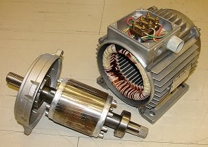
The rotor is the non-stationary part of a rotary electric motor, electric generator or alternator, which rotates because the wires and magnetic field of the motor are arranged so that a torque is developed about the rotor's axis. In some designs, the rotor can act to serve as the motor's armature, across which the input voltage is supplied. The stationary part of an electric motor is the stator. A common problem is called cogging torque.
Friday, July 15, 2011
Electric Generator

In electricity generation, an electric generator is a device that converts mechanical energy to electrical energy. A generator forces electrons in the windings to flow through the external electrical circuit. It is somewhat analogous to a water pump, which creates a flow of water but does not create the water inside. The source of mechanical energy may be a reciprocating or turbine steam engine, water falling through a turbine or waterwheel, an internal combustion engine, a wind turbine, a hand crank, compressed air or any other source of mechanical energy.
Early 20th century alternator made in Budapest, Hungary, in the power generating hall of a hydroelectric station Early Ganz Generator in Zwevegem, West Flanders, Belgium
The reverse conversion of electrical energy into mechanical energy is done by an electric motor, and motors and generators have many similarities. In fact many motors can be mechanically driven to generate electricity, and very frequently make acceptable generators.
Early 20th century alternator made in Budapest, Hungary, in the power generating hall of a hydroelectric station Early Ganz Generator in Zwevegem, West Flanders, Belgium
The reverse conversion of electrical energy into mechanical energy is done by an electric motor, and motors and generators have many similarities. In fact many motors can be mechanically driven to generate electricity, and very frequently make acceptable generators.
Friday, November 14, 2008
Ester Elektronik Digital Display Card Using at Generator Hydrogen Panel
Item : Digital display
Brand :Ester Elektronik
Model : PMO 5405 S4 G2
Supply Voltage : 18 Vdc~ 30 Vdc
Display height :14 mm red light.
Power supply :230V /115 AC
Outer dimension :96 x 48x120mm
Brand : Ester Elektronik
Model : PMO-2160 N3 G3 I
Power consumption : ~ 1.7 W
Type of Measurement:
Channel 1 Counting forward and backward .
Channel 2 for direction.Display : -19999 ….99999 scaling with divider and multiplier.
Power supply :230V /115 AC
Power Supply for sensor: 15 V / 60 mA
Thursday, October 30, 2008
Pepperl fuchs digital card, potentiometer card and converter card at Hydrogen Gas Panel
Pepperl fuchs digital card, potentiometer card and converter card at Hydrogen Gas Panel
Item : Digital input card
Brand : Pepperl fuchs
Model : KFD2-SR2-EX1.W.LB
Supply Voltage: 24 Vdc~ 30 Vdc
Power consumption: ~ 1.7 W
Ambient temp: 55 C
With 3 LED light : Red LED –Power
Green LED- CHK: Yellow - Out
Brand : Pepperl fuchs
Model : KFD2- PT2-Ex1-5
Supply Voltage : 24 Vdc~ 30 Vdc
Power consumption : ~ 1.7 W
Terminal connection type : Terminal 11+ , 12 -,
Ambient temperature : 55 C
Output : 4 mA …. 20 mA
Item: Amplifier Converter Card
Brand : Pepperl fuchs
Model : KFD2-CR – Ex 1.30300
Supply Voltage : 24 Vdc~ 30 Vdc
Power consumption : ~ 1.7 W
Terminal connection type : terminal 1+, 2 -, 3, 0
Ambient temperature : 55 degree C
Monday, March 3, 2008
Brodersen Control - Temperature Converter PXT-10.924 PT128
This signal converter currently using at the Turbine Generator Cubicle for the conversion a temperature to an analogue process signal.
 Brodersen Control Temperature Converter
Specification;
- Manufacturer: Brodersen Control
- Model: PXT-10.924 PT128
- Special Range: 0 to 160 degree C
- Supply: 24 VDC
 Tagging
- Manufacturer: Brodersen Control
- Model: PXT-10.924 PT128
- Special Range: 0 to 160 degree C
- Supply: 24 VDC
 Tagging
While this is the tagging attached to confirm the spec on the back casing. I am not sure whether it is still available in the market or not currently. But if you have problem with this, you may contact the manufacturer.
Friday, February 22, 2008
Digital Temperature Transmitter
At first in my previous post I think this instrumentation device is called temperature or RTD's converter. But when I surfed the internet about this equipment, it's name 'Digital Temperature Transmitter'. Currently used at Turbine Generator area and some areas in power plant.
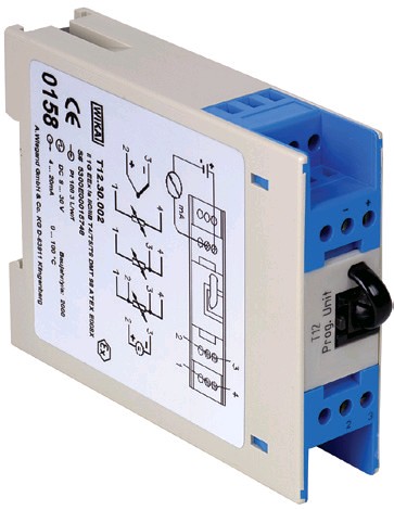 Digital Temperature Transmitter
Application
- Machinery, Plant Construction
- Process Industry
Special Features
- Universal via Window PC
- Isolation voltage 1500VAC between sensor and current loop
- Signalling configurable for sensor burnout and sensor short circuiting
- Machinery, Plant Construction
- Process Industry
Special Features
- Universal via Window PC
- Isolation voltage 1500VAC between sensor and current loop
- Signalling configurable for sensor burnout and sensor short circuiting
 Designation of terminal connectors
 Connection of Programming Unit PU348
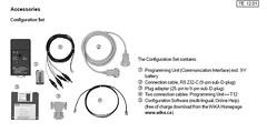 Accessories
On the accessories, I found that there is one configuration software which need to be ordered separetely by enduser. My specification required for this instrumentation device is;
Pt100 3/L/f
DC 9....36V
4 to 20 mA
0.... 160 degree C
How to order? If this device need to be configured first, we need also the software configurator.
Pt100 3/L/f
DC 9....36V
4 to 20 mA
0.... 160 degree C
How to order? If this device need to be configured first, we need also the software configurator.
More details, you can visit WIKA website.
Friday, January 25, 2008
Conductivity Analyser High Alarm Operated at The Generator Panel
High alarm operated. Permit issued to check probe and termination at panel. Service and tighten termination then get reading 0.13 μS/cm. High alarm reset (>0.20 μS/cm). Conductivity range is 0.00 – 1.00 μs/cm. I already list out in the purchasing for next order. You can check the thing here before together with ABB products.

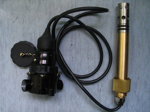
Condenser Hotwell Conductivity Sensor
Manufacturer: ABB 2085-4085
Specification: K = 0.1
Thursday, January 10, 2008
Unit No.3 Generator Stator Terminal Connection RTDs
I got this email last week;
During the unit 3 trip on Saturday 29th December, it was noted that one of the Stator terminal connection point cooling water RTD devices 03MKA11CT611 went off scale, returning to normal about 5-6 hours later. Also, all of the time 03MKA11CT612 was sitting at zero. See attached trend.
While it might look as if the behavior of CT611 is genuine (not fluctuating or spiking), the Alstom Generator expert doesn’t believe that it can genuinely go that high after the generator tripped.
I took the opportunity myself to check the actual loop connections at the DCS and Generator (mA & RTD side of the transducers at the generator marshalling box) – all appear OK.
Could you ask someone to check the RTDs by direct measurement and the RTD-mA transducers by simulation, just to prove that they are working OK.
Also, if you get the chance, the RTD for Stator outlet winding temperature 03MKA11CT505 has been sat at 73-74 degC for the last few weeks without changing.
It would be preferable to do these checks before Unit 3 comes back on load, hopefully within the next day or 2.
Many thanks for your help in advance.
Here is our finding to that problem:
03MKA11CT505 (
| Number cable | Number cable | Result ( Ω ) |
| 1 | 3 | 113.9 |
| 1 | 2 | 114 |
| mA | | |
| 4 | 0 | 0 |
| 8 | 38 | 40 |
| 12 | 79 | 80 |
| 16 | 118 | 119 |
| 20 | 159 | 159 |
Remark Status
1. Check RTD resistant OK
2. Inject mA at DCS OK
3. Check mA at converter card reading 11.36mA converter card
after disconnect cable at converter card reading still 11.36mA faulty.
03MKA11CT611
| Number cable | Number cable | Result ( Ω ) |
| 1 | 3 | 115.5 |
| 1 | 2 | 115.4 |
| A | | |
| 4 | 0.8 | 0.8 |
| 8 | 40.5 | 40.5 |
| 12 | 79.9 | 79.9 |
| 16 | 119.9 | 119.9 |
| 20 | 159.7 | 159.7 |
1. Check RTD resistant OK
2. Inject mA at DCS OK
3. Check mA at converter card reading 7.69mA OK
03MKA11CT612 (
| Number cable | Number cable | Result ( Ω ) |
| 1 | 3 | 113.9 |
| 1 | 2 | 113.8 |
| A | | |
| 4 | 0.2 | 0.2 |
| 8 | 39 | 39 |
| 12 | 78.4 | 78.4 |
| 16 | 119.6 | 119.6 |
| 20 | 159.04 | 159.04 |
2. Inject mA at DCS OK
3. Check mA at converter card reading 3.5mA reading converter card
at output converter card low faulty.
Subscribe to:
Posts (Atom)
